All Points North
Model Railroad Layout Details
We started construction on our layout in
late January 2003. The layout is HO
scale containing 530' of main line,
plus another 230' of track going
down to and around hidden staging, where
there is also a balloon track that
allows entire trains to be turned
around. There is also an HOn3
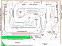
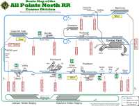
narrow gauge line. The track plan is a
multi-grade (not multi-level) design
that features a single track mainline
with numerous passing sidings. The plan
is free-lanced in both era and location,
and therefore, does not follow any
particular prototype or time period.

The plan includes a large Port area
with: a dock for unloading new autos
from ships into waiting car-carriers, an
intermodal yard, a grain elevator, a
refinery with tank car loading racks and
barge pier, a waterfront scene,
a power plant and other warehouses
supporting rail traffic.
From the coast the layout climbs, making
its way into mountain scenes as well,
and past other industries such as a
paper mill, lumber yard, rail car
maintenance & paint facility, and a
mine. The route also passes through
several towns with numerous industries.
Also being constructed are a transfer
table equipped diesel servicing and
repair facility and a separate steam
facility, complete with a round house.
 The
layout can be run as continuous loop or
point-to-point. The HO scale line has
three industrial switching areas online,
with more on the way. There are four
staging yards - two above our workbench
and two below the main layout
peninsulas, providing a grand total of
25 staging tracks. The
layout can be run as continuous loop or
point-to-point. The HO scale line has
three industrial switching areas online,
with more on the way. There are four
staging yards - two above our workbench
and two below the main layout
peninsulas, providing a grand total of
25 staging tracks.
In 2007 we started holding regular
operating sessions using
RailOp, a computer program designed
to manage car, engine, train, and track
location files – and to create the
paperwork needed to easily move freight
and trains of all types over our
railroad.
Some of the features of the layout are
as follows:
- 30' by 50' layout room
(Original Layout) 50' by 50' layout
room (expansion)
- Over 2600' of track
(Original Layout)
- 30" minimum radius on the main
line
- Number 6 minimum turnout size on
the main line
- Maximum gradient 2-1/2%
- 9 passing sidings (excluding the
yards) that range in length from 13
to 41'. Two of them can be used in
combination for a single siding that
is 56' long!
- 4 staging yards with 25 staging
tracks
- 2 nested 1-1/2 turn helixes
under Mount Willie
- Approximately 100' of HOn3
narrow gauge line
- All HO Scale track is
Atlas Nickel-Silver Code 83.
- Turnouts are a mixture of
Walthers/Shinohara Code 83,
custom hand laid and
BK Enterprises. All turnouts
have been modified to a DCC friendly
format as outlined in the Allan
Gartner's "Wiring
for DCC" turnout pages.
- Switch machines are a
combination of Circuitron Tortoise
and
Switchmaster slow motion
machines. Many of the Tortoise
machines were modified per
Don Crano's web article.
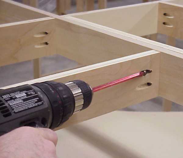
- The bench work is an open grid
design fabricated from 3" wide

strips of ripped 3/4"
furniture-grade plywood, fastened
together with pocket screws. Two
different types of plywood were used
- Baltic Birch and Chinese Birch.
Both types have 13 layers, so they
are very stable. A jig was used to
fabricate various size modules,
however, most of the modules
measured 5' x 30". We had to stick
with 5' long modules since the
Baltic Birch is only sold in 5' x 5'
sheets.
- The roadbed is made from 1/2"
thick
Homasote cut from 4' x 8' sheets
into strips slightly wider than the
track. For curving the Homasote
strips, kerfs about 60% of the strip
width are cut about every 3/4". The
Homasote strips are then glued to
the 3/4" sub-roadbed with Pliobond
II adhesive and then painted with an
earth-toned flat latex paint to
seal.
- The Layout is entirely DCC,
controlled through a
Wangrow System
One Command Station, and is equipped
to support
NCE wireless cabs, using a
Hypergain®
Model HG908P flat patch antenna
to enhance coverage of the NCE RB-01
radio base.
- A separate programming track
where decoders can be programmed
with a "Dog bone" cab or via
mouse-clicks on a PC using the
Decoder Pro software program and
its easy to understand graphical
interface.
- An
18 foot DC test track to test
run engines to tune their
performance before converting them
to DCC.
- The layout has occupancy
detection on the main line and is
connected to a PC using Bruce
Chubb's
Computer/Model Railroad Interface
(C/MRI) system. Ultimately the
layout will be completely signaled
through this system.
-
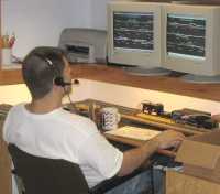
 Via the C/MRI system, signaling
and main line turnouts can be
controlled and train locations can
be monitored from a PC at the
Dispatcher's Desk using a modern CRT
based dispatching system written by
Scott Kurzawski, one of our members.
(A version of this program is
available for download at the
Yahoo CMRI Group site - look for
the APN folder in the Files
section) Via the C/MRI system, signaling
and main line turnouts can be
controlled and train locations can
be monitored from a PC at the
Dispatcher's Desk using a modern CRT
based dispatching system written by
Scott Kurzawski, one of our members.
(A version of this program is
available for download at the
Yahoo CMRI Group site - look for
the APN folder in the Files
section)
With simple mouse clicks on the two
display screens, the dispatcher can
change signal aspect, throw
turnouts, or relinquish control of a
selected turnout back to its fascia
mounted control panel, allowing an
engineer to locally switch a siding.
Click here to view the program's
readme file
Click here for a
screen shot of the display off
both monitors showing the Trains
dispatching program running the All
Points North Model Railroad.

Dispatcher's Screen. Click on it
for a larger view.
The Layout is located in a climate
controlled 2500 sq. ft. building that
was built specifically to house our
layout. The clubhouse sits on 2 acres, and
in addition to the 1500 sq. ft. layout
room, it has a meeting room/library, a
23' wide multi-station workbench with a
vented paint booth, an office, kitchen
and full bath.

All Points North Model Railroad
Association
|

