| NO SMOKING |
|
Our regrets if you are a smoker, as smoking is not allowed in our
building.
Please leave your tobacco in your vehicle.
|
| Photos |
|
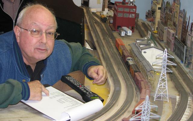
Click on the thumbnails to enjoy some photos of a few of our past
Operating Sessions.
|
| Photos |
|
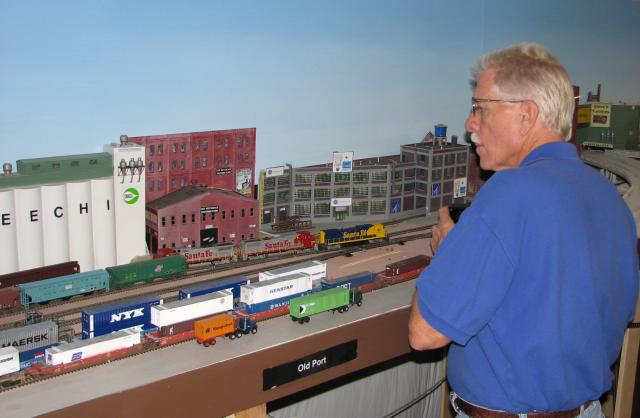
Click on the thumbnails to enjoy some photos of a few of our past
Operating Sessions.
| |
| Operations Orientation |
|
|
|
This information will start basic and
work its way up into more detail.
Skip ahead if you want to. Our
facility is devoted solely to model
railroading, upon arriving, please enter
through our front door.
OK, now that you've found us, you
might be thirsty, or need to use the
restroom after your drive, so here is a
floor plan of our facility showing
where to take care of those needs:
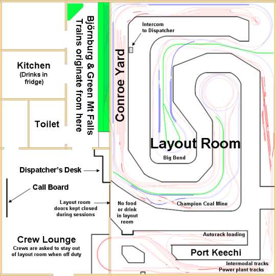
click on
diagram for a printable view
Now that you are refreshed, on the
map above note the Green Mountain Falls
and Björnburg yards shown in green.
These are the terminus yards of APN's
Conroe Division, making these 2
locations the ends of our point-to-point
layout. In an APN operating
session a significant number of trains
will begin and end in these yards.
Other locations that trains begin and
end are also noted on the above plan.
Below is a stretched out view if the
APN mainline, making clear its
point-to-point nature:
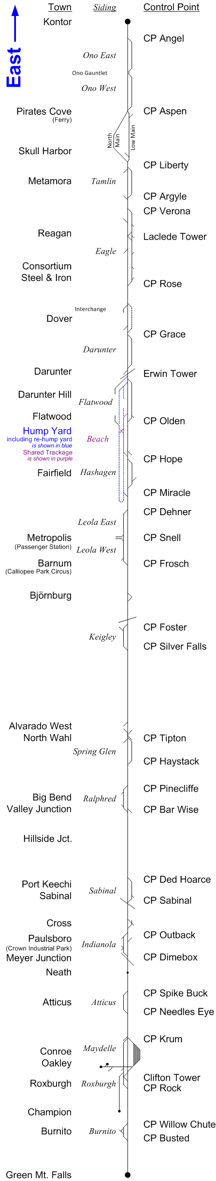
Take note of the 3 columns, listing
Towns, Sidings and CP's, or Control
Points.
These locations are identified by
signage around the layout, either on the
control panels or on separate labels.
Train crew members will receive a
manifest for their assigned train.
Towns where pick-ups or drop offs are to
be made will be listed on these manifests.
Siding and CP names are important in
communicating over the radio with the
dispatcher. These are the
reference points that you will use in
talking with the dispatcher to establish
where you are located at any given time,
or where you will be directed to go as a
part of orders he will give you over the
radio. Before you key up your
microphone to talk to the dispatcher,
determine where you are located in
reference to the nearest CP.
CP's are also very important in that
they mark the boundaries between the
"blocks" of our railroad. Trains
cannot collide with each other if they
are not permitted to occupy the same
section of track at the same time, so
railway lines are divided into sections
known as blocks. In normal
circumstances, only one train is
permitted in each block at a time.
Refer to the section on
signaling to
learn how blocks relate to obeying
signals.
An important part of the dispatcher's
job is to arrange for meets between
trains. As a train crew member,
you must be able to locate the sidings
that the dispatcher directs you to,
where you may be required to hold your
train and wait for one or more trains to
pass you. Note on the map that the
CP names all correspond to the ends of
sidings.
For a more detailed view, click on
the map for a larger version.
|
|
|
You don't need to print out or memorize this map
to enjoy APN. If you elect to become a
crew member you will receive a clipboard that
has a copy of this map for reference, as well as
the following map that shows the entire layout
in schematic view, including all of APN's Conroe
Division and beyond, to Shoshone and Larkspur.
These two beyond-the-layout locations serve as
staging for operating sessions, and also provide
a means to turn around whole trains.
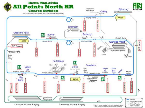
It would be useful to take some
time in advance to familiarize yourself with how
the information is laid out on this map. (click
on the map to see it in more detail) Town
names are shown in blue and siding names are in
italics. The CP names are enclosed in red
boxes. Passenger stops are indicated by
red stop signs, with the names shown in red font
under the little green "Depot" icons.
Although not to scale, this map does do a pretty
decent job of faithfully representing the
trackage as it is laid out in the different
towns.
The track shown in green leads
to staging that is hidden from view under our
layout, and during an operation session it is
not used by train crews. Also, track shown
with a dashed line is not used during operating
sessions.
One feature not shown is our
HOn3
narrow gauge trackage. There are
interchanges between the narrow gauge and the
rest of our layout at the towns of Meyer
Junction and Valley Junction, but as of yet, the
narrow gauge isn't a part of our operating
sessions. But it will be soon!
To view a schematic map of our narrow gauge route,
click here
Industries
What is not shown on either of
the previous maps are the location of all the
industries/buildings. Your Manifest
will direct you to the towns that need to have
pick ups and drop offs made, and specifically at
which industry, and the building or location
within that industry (and in some cases the
specific door or track). You are left in
part to your ingenuity and experience to locate
the right spot within a town that corresponds
with the name on your manifest. In some
cases a notation on a control panel, or a sign
on a building will tell you which is which.
In other cases the structure types along the
different tracks will be the clues you need to
figure out which one is your intended location.
|
|
Rules
Every railroad has its rules, and APN is no
exception, although we don't have near the
number of rules as a real railroad has.
This is primarily because we don't want to
distract from Rule Number 1.
 1. We have freight and passengers to move,
but not at the expense of having FUN! 1. We have freight and passengers to move,
but not at the expense of having FUN!
2. (A) Crews MUST contact the dispatcher before they
depart from their originating terminal and when
tying up at their final destination.
2. (B) Crews
MUST contact and obtain permission from the
Conroe Yard Master before entering the Yard
Limits.
3. (A)
Throttles: APN RR utilizes an NCE DCC
System for control. Operators are encouraged to
familiarize themselves with the throttles prior
to session start. If in doubt, feel free to ask
an APN member.
3. (B) When you are done tying up your train at
its final destination, please turn off the
loco’s lights and sound (if so equipped) and set
the throttle to loco address 0. The latter will
minimize the likelihood of multiple operators
having control of the same loco.
4. (A) Local Control: Turnouts with local
control capability are identified by a blue
track on town control panels. The dispatcher has
to grant local control. When the BLUE LED is
illuminated, you may throw the turnout as you
wish.
4. (B) When leaving an area that you were
granted local control in, please leave switch
thrown in “normal” or mainline position.
5. Signals:
Where signals exist they must be obeyed. Where a
block is not guarded by a signal, Crews MUST
obtain permission from the dispatcher before
entering that block.
6. O.S./Interlockings: The dispatcher can not
align sidings if the OS shows to be occupied. He
may contact you by radio to ask you to reverse
your train to allow you access to your requested
route. OS sections are isolated by an insulating
gap in one rail. APN MOW recently installed
right-of-way signage marking these locations
(Ties painted white and adjoining white posts).
7. Uncoupling: In some areas, the location of
under-track magnets are marked by a white “M”
diamond-shaped sign. In most other areas, skewer sticks should
be aplenty. (APN Special Agents are
investigating reports of “skewer breeding” on RR
property, as they seem to multiply abundantly)
8. (A) Radios: In our “alternate universe”, the
dispatcher is hundreds of miles away, trying to
stay awake watching moving colored lines on a
screen. Cornfield meets don’t make for good
public relations, so keep an ear on the radio
for any changes or instructions from the
dispatcher.
8. (B) Before keying up the radio, monitor for
current transmissions. Be patient and wait your
turn to use the radio airwaves.
8. (C) Always identify yourself when beginning
each radio conversation by announcing your train
number.
9. Non-alcoholic beverages are available to
crews for their enjoyment in the crew lounge.
Food and drinks are not allowed in the layout
room. Smoking is prohibited in the
building.
10. Off duty crews are encouraged to
socialize in the crew lounge, but
please refrain from entering the layout room
unless you are on duty. This minimizes
distractions for crews and adds to the realism
of operating.
11. Pay attention to fascia signage and control
panels. In some locations, upper and lower level
signage are in close proximity.
12. Conroe Yard: As the Conroe yard switcher(s)
finishes preparing a departing train, they are
to notify the dispatcher via the intercom so the
Crew Call Board may be updated.
13. (A) Crew Call Board: The board shows all
trains that are to be run for the session. Any
available crew in the “lounge” may sign up for
the next available train by placing their name tag(s) in the “Crew” column. The board also
indicates relative difficulty of the trains.
Deals may be made between crews, but keep the
fighting to a minimum.
13. (B) When you have tied up your train, mark
the train as “terminated” on the board by posting
the time.
|
OK, maybe at this point you are starting to
feel like we are loading you up with too much
information. Don't worry, there is no test
at the end of this page, and in case you forgot
already, go back up and re-read
Rule number 1,
that is really the most important thing to abide
by. And remember this, at the operating
session there are
going to be APN members around to help you if
you need it. Just ask! And don't be
afraid to ask a "dumb" question. Heck,
that member you ask might not know the answer to
your question either, he might have to go ask
someone else. Or you might come up with
something that no one else has thought of
before, in which case, your questions might spur
thinking that leads to improvements to our
railroad. So please do ask those
questions, and Thank you very much in
advance!
|
Throttles
"Throttles", also known as "cabs", are how
locomotives are controlled at APN. Because
our layout is
DCC, there are no complicated
toggles or rotary switches you have to
understand and fiddle with to gain control over
the section of track your loco is passing
through. With DCC, your cab will control
your train anywhere on the layout. And
using an
NCE
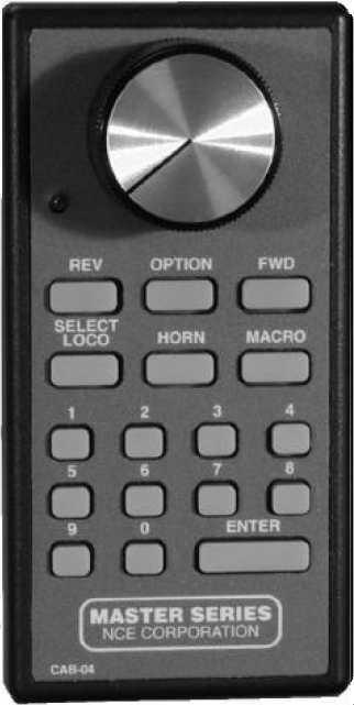
DCC cab is not that hard. Here is
a quick primer on how to use the basic features
of our cabs:
The first thing that you'll need to do is
program your cab with the address of the locomotive or
consist that heads up your train. Don't be
intimidated by the thought of having to do any
programming, it's really very easy to do.
Physically locate your train on the layout, and
note the road number on the lead locomotive of
your train. This is the address number you need to
program into your cab.
Plug your cab into one of the nearby jacks
mounted on the layout fascia.
On your cab, press the "SELECT LOCO" button.
Using the keypad, type in the road number of
your loco. If the road number is 127 or
less, add a leading zero.
Press the "ENTER" key.
That's it! Told you it was easy.
To control your loco, set the direction by
pressing the "REV" or "FWD" buttons.
The big knob is to control your speed.
Turning it clockwise increases speed.
Turning it counter-clockwise to the stop will
halt your engine.
To turn on and off your headlight, press the "0"
button.
If your loco is sound equipped, try the "HORN"
button. Press "2" to toggle the bell on
and off.
To toggle the sound on and off, press the "8"
button.
When you reach your location and tie your train
up, turn off the lights and sound, and program
the cab to loco number "0" |
|
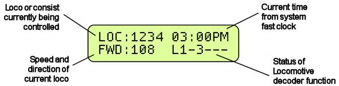
If you get a "dogbone" type cab to use,
it includes a display. This diagram shows
the information a "normal" display will show:
|
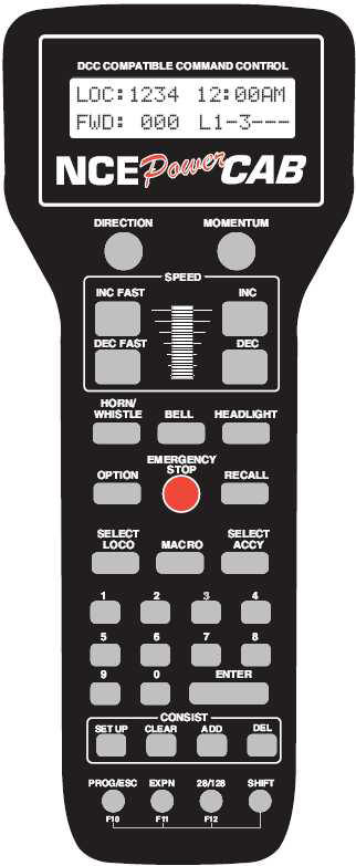
The instructions for using a dogbone cab are
very similar to those for the previous cab.
Physically locate your train on the layout, and
note the road number on the lead locomotive of
your train. This is the number you need to
program into your cab.
Plug your cab into one of the nearby jacks
mounted on the layout fascia.
On your cab, press the "SELECT LOCO" button.
Using the keypad, type in the road number of
your loco. If the road number is 127 or less, add a leading zero.
Press the "ENTER" key. The number you
entered should show in the display.
Actually, if you watch the display, after you
press the "SELECT LOCO" button, it will prompt
you for the loco number. The NCE is pretty
intuitive like that, and is one of the reasons
we chose
NCE over other systems.
To control your loco, set the direction by
pressing the "DIRECTION" button.
Use the controls outlined with the white
rectangle labeled "SPEED" to control
your speed.
You have the choice of using buttons and the
thumb wheel to adjust your speed faster and
slower.
Remember, the display will show your direction
and speed.
To turn on and off your headlight, press the
"HEADLIGHT" button.
If your loco is sound equipped, try the "BELL"
and "HORN/ WHISTLE" buttons.
To toggle the sound on and off, press the "8"
button.
When you reach your location and tie your train
up, turn off the lights and sound, and program
the cab to loco number "0" |
|
Caution: Some of our locomotives have
"momentum" programmed into them. They will
behave just like a real locomotive, and there will be a lag in the time it takes your
train to get to the speed you set with your cab,
and a lag in the time it takes your train to
stop once you set the speed to zero. This
will add to the challenge of running your train,
requiring you to anticipate when and
where you need to stop your train, and to notch down your throttle in advance of
that desired spot.
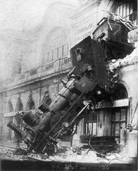 Also,
because our layout is DCC, each train is
controlled independently of every other train,
even on the same stretch of track. So
unlike a conventional DC layout, on our layout you can run
your train faster than the train in front of
you. Or, you can run your train in the
opposite direction of the train in front of you.
Think
Gomez Addams crashing 2 Lionel trains head
on! Also,
because our layout is DCC, each train is
controlled independently of every other train,
even on the same stretch of track. So
unlike a conventional DC layout, on our layout you can run
your train faster than the train in front of
you. Or, you can run your train in the
opposite direction of the train in front of you.
Think
Gomez Addams crashing 2 Lionel trains head
on!
If you get in a situation where you need to
stop right now, and if you have a dogbone,
press that red button right in the middle
labeled "EMERGENCY STOP". You
should only press it once, and your train should
stop immediately. Now this is not
prototypical, but if your train has derailed and
is in danger of falling off the layout and
hitting the floor, the heck with prototypical,
save the lives of those tiny crew members inside that
engine!
The non-dogbone cab (technically known as an
"intermediate" cab) does not have this red
button, but you can still stop your train just
as effectively. First turn the cab dial
all the way counter-clockwise, then yell
"whoa Nelly!" and at the same time take
your finger and place it against the headlight
of your engine and hold it there to stop your
train until the loco no longer pushes against
your finger.
Then resume breathing.
|
Just how fast am I going, anyway? If
your loco has a QSI sound decoder, here's how
you know.
Do you want to operate your train at
prototypical speeds but just don't know what 60
mph "looks" like on an HO scale model?
Most QSI sound decoders (found in many Broadway
Limited, Lionel, PK2, Intermountain and Atlas
models) have a speedometer built in.
If your engine has one of these decoders here's
how to have it tell you how fast you are
travelling. While rolling down the track
press the "F10" key on your dogbone. Your
locomotive will verbally report the loco's speed
in scale miles per hour. If it reports
that your GP9 is travelling at 125 mph, then you
are a tad bit over what the prototype could do,
as they were geared for maximum speeds of from
55 to 89 mph.
Press F10 while at a stop and the locomotive
report its status: whether the long or short
address is enables, its consist ID if it is
assigned to one, and its shutdown state, if it
is in one.
|
Sound:
Previously mentioned was bells and
whistles. We told you how
to make these sounds using the controls
on the throttle, but, just when
are you suppose to use them? Well,
that's not too complicated, either.
At APN we follow a subset of the
General Code of Operating Rules
(GCOR). The GCOR is used by every Class
I railroad west of the Mississippi
River, most of the Class II railroads,
and many Short-line railroads. The
rules as we try to practice them at APN
are as follows (sound equipped locos only):
|
Bells:
Ring the engine bell under any of the following
conditions:
- Before moving, except when making
momentary stop and start switching
movements.
- As a warning signal anytime it is
necessary.
- When approaching public crossings at
grade with the engine in front, as follows:
- If distance permits, ringing must
begin at least 1/4 mile before the
public crossing and continue until the
crossing is occupied.
or
- If distance does not permit, ringing
must begin soon enough before the
crossing to provide a warning and
continue until the crossing is occupied
|
Whistles:
The required whistle signals are illustrated by
“o” for short sounds and “—”
for longer sounds: |
|
Sound |
Indication |
|
Succession of short sounds |
Use when an emergency exists, or persons or
livestock are on the track. When crews on other
trains hear this signal, they must stop. |
|
— — |
Release brakes. Proceed. |
|
o
o o |
When stopped: back up. |
|
—
— o
— |
Approaching public crossings at grade.
Start signal not less than ¼ mile before
reaching crossing, if distance permits. If
distance does not permit, start signal soon
enough before the crossing to provide warning.
Prolong or repeat signal until engine occupies
the crossing. |
|
|
Where to put your "stuff"
 A
train crew's primary responsibility
(beside complying with
Rule no. 1) is to
move their freight or passengers around
the railroad as per the instructions on
their manifest. A
train crew's primary responsibility
(beside complying with
Rule no. 1) is to
move their freight or passengers around
the railroad as per the instructions on
their manifest.
This requires a train crew's focus to be
on the train and the railroad proper,
just as on the prototype.
However, since as yet we haven't had an
operator small enough to squeeze into
one of the
1/87 scale cabs of our
locomotives, all this has to be done
from an adjoining aisle way, with the
train crew required to tote around a
remote cab and a clipboard containing
the manifest and other pertinent
information.
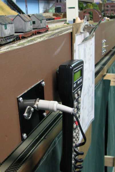
There are times an operator needs a free
hand or two, to throw a turnout or
uncouple a car. Placing a
clipboard or cab on top of the layout
could damage scenery or structures,
derail trains, or cause other
destruction of
Godzilla proportions, so
we ask all our operators to be
considerate and refrain from doing this.
Pretty please?
Rather than an operator having to try to
tuck his cab and clipboard under his
armpits to gain a free hand, we have
conveniently installed a button on the
back of our cabs, and a knob on the back
side of the clipboards. And around
the layout we have clips that the cab's
buttons will slip into.
The photo to the right shows how to use
these conveniences. The knob on
the clipboard is just hung over the lip
of the fascia. (I wish we could take
credit for coming up with this clever
idea, but we got it from seeing a photo
Andrew Keeney had posted online of his
Nashville Road layout, that fortuitously
for us, included a glimpse of a
clipboard with a similar, simple wooden
drawer pull knob attached)
|
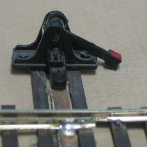
Uncoupling Techniques
 Speaking
of uncoupling, as mentioned in
Rule no.
7, we do have some locations equipped
with uncoupler magnets. Some are
visible between the ties, while others
are hidden under the ballast, and are
identified by a trackside white,
diamond-shaped sign with the letter "M"
on it (refer to photo below). Speaking
of uncoupling, as mentioned in
Rule no.
7, we do have some locations equipped
with uncoupler magnets. Some are
visible between the ties, while others
are hidden under the ballast, and are
identified by a trackside white,
diamond-shaped sign with the letter "M"
on it (refer to photo below).
If you don't know how to use
uncoupler
magnets,
click here
When there isn't a magnet available at
the location you need it, look around
for one of the long, very slender
pointed sticks (bamboo skewer) placed
around the layout.
Then refer to the animation at the right
on how to use this skewer to uncouple a
car. (click on the picture for a
storyboard version of this technique)
A couple of helpful tips:
Introduce some slack in the couplers
before using the skewer;
Limit how far the skewer point goes in, to
prevent binding;
After the lips of the knuckles “roll”
clear of each other, push horizontally
against one of the coupler heads to
separate the cars
|
This photo is to illustrate two
different marker types used along APN's
right-of-way to identify features
important to operations:
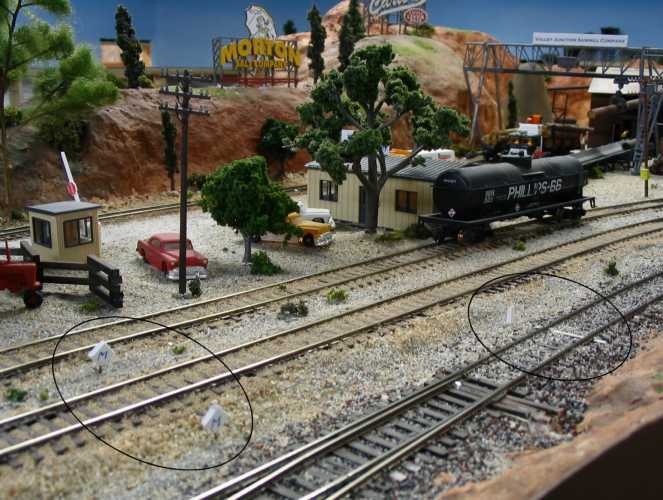
They are shown circled and are:
- The 2 white diamond-shaped signs
indicate that there are uncoupling magnets
located under the ties of the adjoining
tracks
- The white post adjacent to the tie that
is painted white marks the location of the
end of a block and an "OS" section
Refer to Rule nos. 5, 6 and
7 and the section on
signals
for the significance of these two features.
To elaborate on the latter, when required to
stop at a given CP by the Dispatcher, or for any
other reason, you must keep your train from
crossing over an OS boundary marked with the
white tie. Just like on the prototype, if
your train has crossed over this boundary, even
by several (scale) inches, the train detection
circuitry will show your train as occupying both
blocks. The CTC system then locks the
associated turnout, so it can not be remotely
actuated. This is a safety feature to
prevent a turnout from being thrown under a
train. To be able to do anything related
to that turnout, to either throw it or give you
local control, the Dispatcher has to request
that you back up your train to clear the OS.
OS sections also are the dividing points between
the blocks of the railroad.
|
|
|
Turnout indication There are 2 primary
designs of indicator lights in use on control
panels around the layout that show the position
of turnouts. Examples of these 2 designs
are shown below.
|
c.jpg)
This is the older design, and it consists of a
single, 2-color LED for each turnout. The
color of the LED indicates which route the
turnout is aligned for. Green indicates
the through route, and red the divergent route. |
|
c.jpg)
This is our newer design, with a yellow LED on
each leg of the turnout. The LED that is
lit indicates the route the turnout is aligned
to. This is more user-friendly for the
color-blind among us. |
How to Operate Hand Throws
The majority of our
turnouts are motor-driven
and operated from a control panel. (During an
operating session, turnouts on the mainline will
be controlled by the Dispatcher, unless local
control is granted).
But there are, and probably always will be turnouts
on our layout
that are operated by using a hand throw.
As simple as they may seem, there is a bit of
technique to properly use one of these hand
throws, and this is described in the pictures
and captions, below.
Other layout owners have reported that an
alternative to prevent this type of turnout from
being over-thrown is to hammer in a couple of
nails on either side of the throw, leaving the
nail head protruding up and under, and acting as
a stop for the hand throw arm. But don't
you think we can all be disciplined enough to
learn to operate this device correctly, and not
have to resort to using nails as a crutch? Because protruding nails just don't look like
anything prototypical on the real railroads. |
|
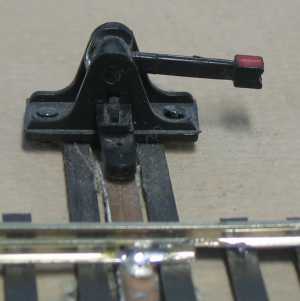
Correct:
The
Throw arm is in a near horizontal position.
There is a slight “indent” that you will feel as
you push the throw arm to
this position. Rotating the arm to this position
and no further is gentler on
the mechanism and it makes it easier for the
next operator to get a grasp on the throw arm.
|
|
Incorrect:
Throw arm is pushed until the head hits the
ground. This position puts additional stress on
the machine itself, and on the points of the
turnout, leading to early failure of both.
It also makes it more difficult for the next
operator that comes along to get a hold of the
arm to throw it the other way. |
|
Manifests
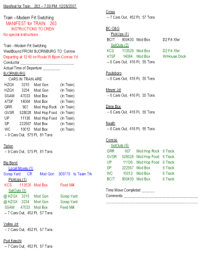 Here
is a sample Manifest for Train Number
263. A Manifest is generated for
every train to be run in an operating
session. An operator signing on as
the Train Crew for a train will receive
a clipboard that includes a Manifest for
that train, a Rules Book and a Route Map
of the APN Conroe Subdivision. Here
is a sample Manifest for Train Number
263. A Manifest is generated for
every train to be run in an operating
session. An operator signing on as
the Train Crew for a train will receive
a clipboard that includes a Manifest for
that train, a Rules Book and a Route Map
of the APN Conroe Subdivision.
These Manifests are created by the software
program
RailOp. Listed in the 2 columns of
this report are the locations the train
originates from and terminates in, and other
towns/locations that will be traveled through.
Town/location names are underlined, as shown in
the detail figure below, and each
town/location's entry is followed by the number
of cars leaving that location and the train's
length and weight.
Switching assignment entries on the Manifest are color coded to assist
the Train Crew in performing their duties:
> Cars that are picked up along the route to
be set-out before the train's terminal
is reached are printed in red as an aid in deciding where
to block the car in the train. All other
PickUps are in black
> SetOuts are shown in Green.
> Local Moves (within same town) are Blue.
Click on the photo for a larger image.
|
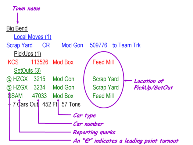
The following is an enlargement of
one section of the above Manifest,
showing the entries for the town of Big
Bend. The lettering in italics
describe the information contained on
the Manifest.
|
|
|
Switch Lists - Conroe Yard Master
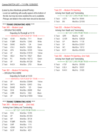
Here is a sample Switch List for the Yard
Master job in the Conroe
Classification Yard.
You can click on it for a larger version.
It shows trains that will originate from and/or
terminate at the Conroe Yard.
For each train that originates from Conroe Yard,
it is the responsibility of the Conroe Yard
Master to assemble the cars listed for each
train, blocked in the order they appear on the
list. The order is relative to the
direction the train will depart, where odd
numbered trains will head East and even numbered
trains will head West.
Once a train is assembled the Yard Master is to
notify the Dispatcher via the intercom.
No movements within the yard limits can be
performed without the permission of the yard
master. Engineers wishing to enter or
depart from the yard with their train must
obtain this approval via a radio request (see Rule no. 2B).
During the course of an operating session the
Operations Superintendent may give the yard
master an updated list. This list might
overlap with the switch list the yard master is
currently working from. It is the duty of
the yard master to compare the new list to the
old and strike out those trains on the new list
that have already been made up.
The Port Keechi Yard Switcher will receive a
similar list, and the use of this list is
comparable to its use in Conroe Yard. |
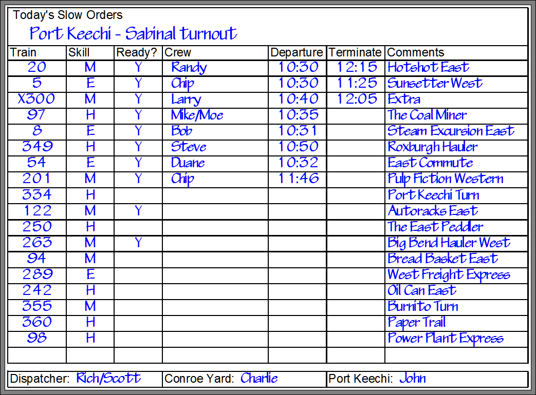
Crew Call Board
Hanging in the Crew Lounge is our "Crew Call
Board". It contains a listing of all the
trains to be available for the Operating
Session, and is for use by Operators to sign up
for train assignments. Its use is
relatively straight-forward, but refer to
Rule no. 13.
More detailed information on each train can
be found by reading through the Train Manifests,
which are on clipboards maintained by the
Superintendent of Operations, and will be
available in the Crew Lounge. The contents
of a train manifest were described above.
Upon deciding on a train to run, an Operator
adds his name to the "Crew" column of the Call
Board, picks up the clipboard for the
chosen train, along with a cab and a radio.
Upon locating his train, and prior to departure,
the Operator should write down the time in the
"Departure" column, and in the appropriate place
on the Train Manifest, and per
Rule no. 2, call the Dispatcher and get
approval before moving your train.
Upon completion of his route, the Operator
should notify the Dispatcher, and write down the
time of arrival in the "Terminate" column of the
Call Board and on the Manifest. If any
difficulties were encountered during your run,
or you have any feedback or suggestions about
this train or the layout or the organization of
the operating session, write them on the
Manifest before turning it in to the Operations
Superintendent.

Diagram of the "Crew Call
Board" showing a sample of one of our sessions
in progress
Also shown on the Call Board are
any speed restrictions in place for the day, and
the names of the Dispatcher, Conroe Yard Master
and Port Keechi Yard Switcher on duty.
Operating Sessions can vary in length from
several hours to most of a day. This
flexibility is possible by choosing how many of
the trains on the Call Board are run during the
given session. It is not necessary that
they all be run, as RailOp can start the next
operation session where the previous session
left off. The decision on how many trains
to complete can be made "on-the-fly" as the
session progresses. Factors such as the
skill level and number of Operators can cause a
session to go faster or take longer than
originally estimated, so the ability to make
adjustments is a convenience that adds to the
enjoyment of the participants. Always
remember Rule no. 1!
In a "Normal " Operating Session,
the number of participants desirable are:
1 -
Dispatcher
1 - Yard Master - Conroe Classification Yard
1 - Yard Switcher - Port Keechi
Yards
7 - Road Engineers (can get by with as few
as 5)
Optional - The "Hole" (usually filled by an
APN member)
Operations Superintendent (A member of
the APN Operations Committee)
A few additional people can be accommodated
(especially newbies) by having 2 persons
assigned to train crew: an
Engineer to drive the train, and the
Conductor, who supervises the engineer
and manages the paperwork. The
limiting factor is the space available in
the layout room aisle ways.
|
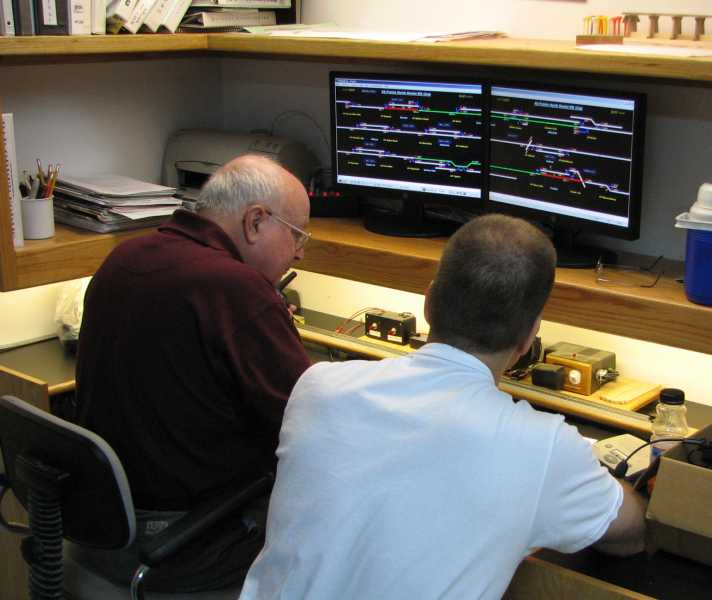
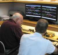 Dispatching 101 Dispatching 101
Imagine that you are in the tiny cab of
your locomotive, and then imagine how
much of the railroad you can actually
see from the vantage point of that tiny
window. Unlike standing in the
aisle towering over the layout, from
inside that cab you can see ahead very
little. So it is on real
railroads, and there engineers rely on
signal systems
and dispatchers to be able to "see" what
trains lie ahead of them.
On our railroad, the Dispatcher can see
what blocks have trains in them, and
with this knowledge, directs the
movement of trains over the APN Conroe
Division's mainline and sidings, making
sure in the process that trains don't
collide. In performing this duty,
our Dispatcher
relies on a Dispatcher's Panel which
allows him to monitor the location and
movement of trains, and operate track
switches (turnouts) and the traffic
signals that tell trains to stop or
change their speed.
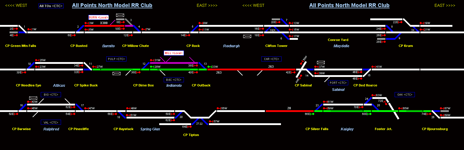
A portion of the Dispatcher's Panel is
shown in the diagram below.
Green Mountain Falls, the western extent
of the Conroe Division, is shown in the
upper left hand corner of the panel, and
Björnburg, the eastern most extent, is
at the lower right hand corner of
the panel. The track plan wraps
around similarly to the text in this
paragraph, i.e. the right hand end of
the upper track continues to the left
hand end of the middle track,
immediately below it. Following
that track to the right hand edge of the
panel, it connects with the left hand
end of the track shown in the bottom
track segment on the panel.
All turnouts that can be controlled
remotely by the Dispatcher are drawn on
the panel with a wide line for the
diverging route, and are
numbered sequentially from West to East.
All other turnouts leaving the mainline
or sidings are shown with a narrower
line, and are not numbered.
The Dispatcher throws those turnouts
over which he has control by placing the
cursor over the turnout diagram on the
panel, and right-clicking the mouse.
The route these
turnouts are aligned to will be shown as
a white line.
Just like on the prototype, there is an
interlock that prevents the Dispatcher
from throwing a turnout under a train.
If a train has fouled the OS of a
turnout, that turnout's diagram will
appear red on the panel, and the
Dispatcher will not be able to throw it.
The train will have to back up and clear
the OS before the Dispatcher can regain
control of the turnout. Refer to
Rule no. 6.
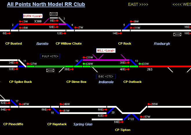
A portion of the Dispatcher's Panel.
Click on it for a larger view showing the entire
panel. Referring to
one of the maps shown earlier on this page and
comparing it to the Dispatcher Panel above, the
names of CP locations are shown on the panel in
yellow
text .
Siding names are shown in
light
blue italics
.
Town are not all labeled as such.
Instead, there are labels only at those
locations where there are turnouts from the
mainline or siding that can be controlled either
by the Dispatcher, or at his election, by the
local train crew (refer to Rule no. 4).
These labels are contained in boxes on the
diagram, and show either an abbreviation for the
Town's name, or for a major industry near the
turnout. Either <Local> or <CTC> will
appear after the abbreviation, indicating who
has control of the turnout. The Dispatcher
can toggle who has this control of the turnout
by moving the cursor over a box and clicking the
left mouse button.
When the train crew has control of the
turnouts, <Local> will appear in the box,
the box background color will turn white and the
appropriate block of track and the effected
turnouts will show as purple
 on the display. In addition, there will be
a blue LED that lights up on the layout fascia
near the turnout, on the Control Panel that has
the toggle switches that will now control those
turnouts.
on the display. In addition, there will be
a blue LED that lights up on the layout fascia
near the turnout, on the Control Panel that has
the toggle switches that will now control those
turnouts.
A red line
 on the panel indicates blocks that are occupied
by a train. A white line indicates
unoccupied track.
on the panel indicates blocks that are occupied
by a train. A white line indicates
unoccupied track.
A green line
 on the panel indicates the block(s) of track ahead
of a train that the Dispatcher has set the
signals for, giving that train authority.
The direction of that authority is indicated by
a black arrow superimposed on top of the green
line, and by the numbered green signal marker
indicators (
on the panel indicates the block(s) of track ahead
of a train that the Dispatcher has set the
signals for, giving that train authority.
The direction of that authority is indicated by
a black arrow superimposed on top of the green
line, and by the numbered green signal marker
indicators (
 ). The Dispatcher sets the signals by
left-clicking on the appropriate red signal
symbols ahead of a train. The signals will
clear (
). The Dispatcher sets the signals by
left-clicking on the appropriate red signal
symbols ahead of a train. The signals will
clear (
 ) when the train enters the block, but can be cleared
manually by double clicking on the symbol.
) when the train enters the block, but can be cleared
manually by double clicking on the symbol.
Once the Dispatcher has set a route for a train,
he can right-click on the red line for a train,
and enter an identifier tag for that train.
Typically the information entered in the tag
would be the train number. Once entered,
this tag will display above or below the red block of
track occupied by that train, and the tag will
follow the train on the screen as it moves from
block to block. The train symbol appears
on the screen in light grey bold font, as shown
in this example:
 which appears on the sample screen above on the
Burnito Siding.
which appears on the sample screen above on the
Burnito Siding.
Passenger stations, depots and stops are
indicated by this symbol
 on the panel.
The Dispatcher passes orders and other
communications to Train Crews via 2-way radio,
and communicates with the Conroe Yard Master via
an intercom. |
|
|
|
|
|
|
Signals:
During APN Operating Sessions, control of trains is via
Centralized Traffic Control, or CTC. All of the
signals that will eventually be associated with CTC are not
installed on our railroad yet, which increases the importance of
communications between train crews and the dispatcher via radio.
For those stretches of the APN mainline that are signaled, a
train crew can safely operate their train by obeying those
signals. This section gives an overview of what the
signals in use on our railroad mean.
Our railroad is divided up into "blocks," and each block
boundary is designated by a Control Point, or "CP."
Signals, when they are present, are located primarily at the
start of each block. They govern whether a train may enter
the block they protect.
It is important to remember that, since our railroad is
not completely signaled yet, a train crew cannot rely completely
on signals to identify where blocks start and end. The
locations of all CP's are shown on our
Route
Maps, are also labeled on the control panels around the
layout, and trackside are identified by white painted ties and
posts at each block boundary. As you run your train down
the mainline, you must not just be on the lookout for the next
signal, you also must follow your map or observe the control
panels, or watch for the next white painted tie to make sure you
don't overrun into the next block, if it happens to be unsignaled. You must get clearance from the
dispatcher
before entering any unsignaled block. In unsignaled
territory, he is your "eyes" and knows whether those blocks
ahead have a train in them or not. |
|
Signal Basics:
To understand signals, you must
learn these two building blocks. Once you know these two
concepts, how to obey signals becomes more intuitive.
Concept 1: Signal Colors and what they mean
|
|
The
color tells you how many block past the signal are
unoccupied |
Name |
Action to take |
|
n |
0 |
Red |
Stop |
Stop.
Unless flashing red, then stopping is not required,
and you may proceed at a restricted speed, but be
prepared to stop. |
|
n |
1 |
Yellow |
Approach |
Proceed, reduce to medium speed, be prepared to stop
at the next signal (or CP).
If flashing yellow, reduction in speed not required.
|
|
n |
2 |
Green |
Clear |
Proceed |
|
|
Note that when a light is flashing, the number of unoccupied
blocks ahead remain the same. The blinking indicates that
for the color shown, the signal is less restrictive than if the
same color was shown but was not flashing. So for example,
yellow means that 1 block past the signal is unoccupied, but the
block following that is occupied. You may proceed past the
signal at medium speed if the signal shows a steady yellow
light. If the light is flashing yellow, you may proceed,
but are not required to reduce your speed. In either case,
you must be prepared to stop at the start of the next block,
which will be at the next Control Point, where there may or may
not be another signal. (If there is not, remember the rule
stated earlier, you may not enter an unsignaled block without
the permission of the dispatcher). |
|
Concept 2: Multiple Signal Heads
|
|
 |
When
there are stacked signal heads, as depicted here, the
upper signal is for the mainline, and the lower signal
for a diverging route, such as a passing siding.
|
 |
|
|
|
|
1 + 2 = Putting it together So with these two concepts,
here's what you do. When you approach a signal, if the
upper color is green or yellow, proceed ahead on the mainline.
If it is red, look for a second color, below the first. If
there is none, or if it is also red, then you must stop.
If the lower signal is green or yellow, then you may proceed,
but you are being routed into the diverging route. The
exception is when a red signal is flashing, in which case
stopping is optional, but if you don't stop, you must slow down
to restricted speed and be able to stop your train in half the
distance between you and any opposing train, broken rail,
improperly thrown turnout or other obstruction.
Hopefully if you think about it in these terms it will make
sense, and you can figure out what any signal combination means,
without the need for showing pictures of all the possible
combinations of signals here.
|
|
Factoid: The single lens search light signals shown above on
the right will be short lived on the APN railroad, as they are
due to be replaced by signal head types that contain individual
lenses for green, yellow and red. This to accommodate our
color-blind operators who can not all distinguish between the 3
colors. |
More Information:
For a more comprehensive set of
information on using our layout,
click here
Want to see an Operating Session in pictures?
click here
The following are being contemplated as
future additions to this page:
Description of the available jobs
Control panels - local control LED
FRS Radio use 101
Guests will not
need to bring anything except their
enthusiasm for operations. We have
enough radio handsets for all, so you
don't have to bring your own. However,
we do not have enough headsets to go
around. We use FRS radios. If you have
an FRS radio with a headset that you are
partial to, please feel free to bring it
to use at the session.
CTC
|
|
Press your
"HOME" key
at any time
to return to
the top of
this page. |
|
Updated on
01/11/2026 |
|
|
|